
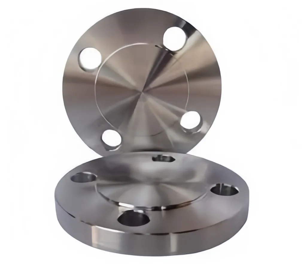
Blind Flange
 |
 |
|
|
1. Materials:
Carbon Steel: ASTM A105, ASTM A350 LF1, LF2, LF3, A36, 16Mn, etc
Stainless Steel: ASTM A 182, A 240 F 304, 304L, 304H, 316, 316L, 316Ti, 310, 310S, 321, 321H, 317, 347, 347H, 904L
Alloy Steel: A182 F1, F5, F9, F11, F12, 22, F22, F91, etc
Duplex Stainless Steel: ASTM A 182 – F51, F53, F55, S31803, S32205, S32550, S31254, SMO254, S32750, S32760, S32950.
Copper Alloy Steel: ASTM / ASME SB 111 UNS NO. C 10100, C 10200, C 10300, C 10800, C 12000, C 12200, C 70600, C 71500, ASTM / ASME SB 466 UNS NO. C 70600 ( CU -NI- 90/10), C 71500 ( CU -NI- 70/30)
Nickel Alloy: ASTM / ASME SB 336, ASTM / ASME SB 564 / 160 / 163 / 472, UNS 2200 (NICKEL 200), UNS 2201 (NICKEL 201 ), UNS 4400 (MONEL 400 ), UNS 8020 ( ALLOY 20 / 20 CB 3 ), UNS 8825 INCONEL (825), UNS 6600 (INCONEL 600 ), UNS 6601 (INCONEL 601), UNS 6625 (INCONEL 625), UNS 10276 (HASTELLOY C 276)
For detial dimensions and catalogue of Reducing Flanges please contact with us now sales@attpipeline.com
2. Standards:
ANSI/ASME B16.5, B16.36, B16.47, AWWA C207, DIN, BS, SABS/SANS, MSS SP44, ISO, API Flange, etc
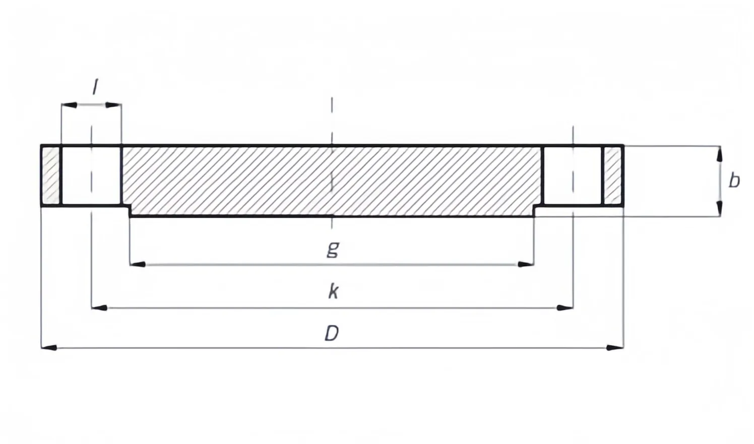
Dimensions & Masses of ANSI B16.5 Blind Flange Class 150/300/600
| ANSI, ASME, ASA, B16.5 150lb/sq.in. Blind Flange RF | |||||||
| ø | D | b | g | k | Holes | l | Kg. |
| 1/2" | 88,9 | 11,1 | 34,9 | 60,3 | 4 | 15,9 | 0,400 |
| 3/4" | 98,4 | 12,7 | 42,9 | 69,8 | 4 | 15,9 | 0,700 |
| 1" | 107,9 | 14,3 | 50,8 | 79,4 | 4 | 15,9 | 0,900 |
| 1 1/4" | 117,5 | 15,9 | 63,5 | 88,9 | 4 | 15,9 | 1,300 |
| 1 1/2" | 127,0 | 17,5 | 73,0 | 98,4 | 4 | 15,9 | 1,600 |
| 2" | 152,4 | 19,0 | 92,1 | 120,6 | 4 | 19,0 | 2,600 |
| 2 1/2" | 177,8 | 22,2 | 104,8 | 139,4 | 4 | 19,0 | 4,100 |
| 3" | 190,5 | 23,8 | 127,0 | 152,4 | 4 | 19,0 | 5,000 |
| 3 1/2" | 215,9 | 23,8 | 139,7 | 177,8 | 8 | 19,0 | 6,400 |
| 4" | 228,6 | 23,8 | 157,2 | 190,5 | 8 | 19,0 | 7,100 |
| 5" | 254,0 | 23,8 | 185,7 | 215,9 | 8 | 22,2 | 9,000 |
| 6" | 279,4 | 25,4 | 215,9 | 241,3 | 8 | 22,2 | 11,800 |
| 8" | 342,9 | 28,6 | 269,9 | 298,4 | 8 | 22,2 | 21,000 |
| 10" | 406,4 | 30,2 | 323,4 | 361,9 | 12 | 25,4 | 30,000 |
| 12" | 482,6 | 31,7 | 381,0 | 431,8 | 12 | 25,4 | 45,000 |
| 14" | 533,4 | 34,9 | 412,7 | 476,2 | 12 | 28,6 | 59,000 |
| 16" | 596,9 | 36,5 | 469,9 | 539,9 | 16 | 28,6 | 79,000 |
| 18" | 635,0 | 39,7 | 533,4 | 577,8 | 16 | 31,7 | 97,000 |
| 20" | 698,5 | 42,9 | 584,2 | 635,0 | 20 | 31,7 | 124,000 |
| 22" | 749,3 | 46,0 | 641,2 | 692,1 | 20 | 34,9 | 151,000 |
| 24" | 812,8 | 47,6 | 692,1 | 749,3 | 20 | 34,9 | 188,000 |
NOTE:
1. Class 150 flanges except Lap Joint will be furnished with 0.06 (1.6mm) raised face, which is included in ‘Thickness’ (C) and ‘Length through Hub’ (Y1), (Y3).
2. For Slip-on, Threaded, Socket Welding and Lap Joint Flanges, the hubs can be shaped either vertical from base to top or tapered within the limits of 7 degrees.
3. Blind Flanges may be made with the same hub as that used for Slip-on Flanges or without hub.
4. The gasket surface and backside (bearing surface for bolting) are made parallel within 1 degree. To accomplish parallelism, spot facing is carried out according to MSS SP-9, without reducing thickness (C).
5. Depth of Socket (D) is covered by ANSI B 16.5 only in sizes through 3 inch, over 3 inch is at the manufacturer’s option.
| ANSI, ASME, ASA, B16.5 300lb/sq.in. Blind Flange RF | |||||||
| ø | D | b | g | k | Holes | l | Kg. |
| 1/2" | 95,2 | 14,3 | 34,9 | 66,7 | 4 | 15,9 | 0,700 |
| 3/4" | 117,5 | 15,9 | 42,9 | 82,5 | 4 | 19,0 | 1,200 |
| 1" | 123,8 | 17,5 | 50,8 | 88,9 | 4 | 19,0 | 1,500 |
| 1 1/4" | 133,3 | 19,0 | 63,5 | 98,4 | 4 | 19,0 | 2,000 |
| 1 1/2" | 155,6 | 20,6 | 73,0 | 114,3 | 4 | 22,2 | 2,900 |
| 2" | 165,1 | 22,2 | 92,1 | 127,0 | 8 | 19,0 | 3,400 |
| 2 1/2" | 190,5 | 25,4 | 104,8 | 149,2 | 8 | 22,2 | 5,100 |
| 3" | 209,5 | 28,6 | 127,0 | 168,3 | 8 | 22,2 | 7,000 |
| 3 1/2" | 228,6 | 30,2 | 139,7 | 184,1 | 8 | 22,2 | 8,900 |
| 4" | 254,0 | 31,7 | 157,2 | 200,0 | 8 | 22,2 | 11,800 |
| 5" | 279,4 | 34,9 | 185,7 | 234,9 | 8 | 22,2 | 15,500 |
| 6" | 317,5 | 36,5 | 215,9 | 269,9 | 12 | 22,2 | 21,300 |
| 8" | 381,0 | 41,3 | 269,9 | 330,2 | 12 | 25,4 | 35,200 |
| 10" | 444,5 | 47,6 | 323,8 | 387,3 | 16 | 28,6 | 57,000 |
| 12" | 520,7 | 50,8 | 381,0 | 450,8 | 16 | 31,7 | 82,000 |
| 14" | 584,2 | 54,0 | 412,7 | 514,3 | 20 | 31,7 | 106,000 |
| 16" | 647,7 | 57,1 | 469,9 | 571,5 | 20 | 34,9 | 140,000 |
| 18" | 711,2 | 60,3 | 533,4 | 628,6 | 24 | 34,9 | 178,000 |
| 20" | 774,7 | 63,5 | 584,2 | 685,8 | 24 | 34,9 | 223,000 |
| 22" | 838,2 | 66,7 | 641,2 | 742,9 | 24 | 41,3 | 270,000 |
| 24" | 914,4 | 69,8 | 692,1 | 812,8 | 24 | 41,3 | 345,000 |
NOTE:
1. Class 300 flanges except Lap Joint will be furnished with 0.06 (1.6mm) raised face, which is included in ‘Thickness’ (C) and ‘Length through Hub’ (Y1), (Y3).
2. For Slip-on, Threaded, Socket Welding and Lap Joint Flanges, the hubs can be shaped either vertical from base to top or tapered within the limits of 7 degrees.
2. For Slip-on, Threaded, Socket Welding and Lap Joint Flanges, the hubs can be shaped either vertical from base to top or tapered within the limits of 7 degrees.
4. The gasket surface and backside (bearing surface for bolting) are made parallel within 1 degree. To accomplish parallelism, spot facing is carried out according to MSS SP-9, without reducing thickness (C).
5. Depth of Socket (D) is covered by ANSI B 16.5 only in sizes through 3 inch, over 3 inch is at the manufacturer’s option.
| ANSI, ASME, ASA, B16.5 600lb/sq.in. Blind Flange RF | |||||||
| ø | D | b | g | k | Holes | l | Kg. |
| 1/2" | 95,2 | 14,3 | 34,9 | 66,7 | 4 | 15,9 | 0,700 |
| 3/4" | 117,5 | 15,9 | 42,9 | 82,5 | 4 | 19,0 | 1,200 |
| 1" | 123,8 | 17,5 | 50,8 | 88,9 | 4 | 19,0 | 1,500 |
| 1 1/4" | 133,3 | 20,6 | 63,5 | 98,4 | 4 | 19,0 | 2,000 |
| 1 1/2" | 155,6 | 22,2 | 73,0 | 114,3 | 4 | 22,2 | 3,200 |
| 2" | 165,1 | 25,4 | 92,1 | 127,0 | 8 | 19,0 | 4,300 |
| 2 1/2" | 190,5 | 28,6 | 104,8 | 149,2 | 8 | 22,2 | 6,000 |
| 3" | 209,5 | 31,7 | 127,0 | 168,3 | 8 | 22,2 | 8,000 |
| 3 1/2" | 228,6 | 34,9 | 139,7 | 184,1 | 8 | 25,4 | 10,500 |
| 4" | 273,0 | 38,1 | 157,2 | 215,9 | 8 | 25,4 | 18,000 |
| 5" | 330,2 | 44,4 | 185,7 | 266,7 | 8 | 28,6 | 28,500 |
| 6" | 355,6 | 47,6 | 215,9 | 292,1 | 12 | 28,6 | 35,500 |
| 8" | 419,1 | 55,6 | 269,9 | 349,2 | 12 | 31,7 | 58,000 |
| 10" | 508,0 | 63,5 | 323,8 | 431,8 | 16 | 34,9 | 98,000 |
| 12" | 558,8 | 66,7 | 381,0 | 488,9 | 20 | 34,9 | 125,000 |
| 14" | 603,2 | 69,8 | 412,7 | 527,0 | 20 | 38,1 | 151,000 |
| 16" | 685,8 | 76,2 | 469,9 | 603,2 | 20 | 41,3 | 215,000 |
| 18" | 742,9 | 82,5 | 533,4 | 654,0 | 20 | 44,4 | 287,000 |
| 20" | 812,8 | 88,9 | 584,2 | 723,9 | 24 | 44,4 | 366,000 |
| 22" | 869,9 | 95,2 | 641,2 | 777,9 | 24 | 47,6 | 437,000 |
| 24" | 939,8 | 101,6 | 692,1 | 838,2 | 24 | 50,8 | 532,000 |
NOTE:
1. Class 600 flanges except Lap Joint will be furnished with 0.25 (6.35mm) raised face, which is not included in ‘Thickness’ (C) and ‘Length through Hub’ (Y1), (Y3).
2. For Slip-on, Threaded, Socket Welding and Lap Joint Flanges, the hubs can be shaped either vertical from base to top or tapered within the limits of 7 degrees.
3. Blind Flanges may be made with the same hub as that used for Slip-on Flanges or without hub.
4. The gasket surface and backside (bearing surface for bolting) are made parallel within 1 degree. To accomplish parallelism, spot facing is carried out according to MSS SP-9, without reducing thickness (C).
5. Dimensions of sizes 1/2 through 3 1/2 are the same as for Class 400 Flanges.
6. Depth of Socket (D) is covered by ANSI B 16.5 only in sizes through 3 inch, over 3 inch is at the manufacturer’s option.
2. Standards:
ANSI/ASME B16.5, B16.36, B16.47, AWWA C207, DIN, BS, SABS/SANS, MSS SP44, ISO, API Flange, etc
Dimensions & Masses of ANSI B16.5 Blind Flange Class 150/300/600
| ANSI, ASME, ASA, B16.5 150lb/sq.in. Blind Flange RF | |||||||
| ø | D | b | g | k | Holes | l | Kg. |
| 1/2" | 88,9 | 11,1 | 34,9 | 60,3 | 4 | 15,9 | 0,400 |
| 3/4" | 98,4 | 12,7 | 42,9 | 69,8 | 4 | 15,9 | 0,700 |
| 1" | 107,9 | 14,3 | 50,8 | 79,4 | 4 | 15,9 | 0,900 |
| 1 1/4" | 117,5 | 15,9 | 63,5 | 88,9 | 4 | 15,9 | 1,300 |
| 1 1/2" | 127,0 | 17,5 | 73,0 | 98,4 | 4 | 15,9 | 1,600 |
| 2" | 152,4 | 19,0 | 92,1 | 120,6 | 4 | 19,0 | 2,600 |
| 2 1/2" | 177,8 | 22,2 | 104,8 | 139,4 | 4 | 19,0 | 4,100 |
| 3" | 190,5 | 23,8 | 127,0 | 152,4 | 4 | 19,0 | 5,000 |
| 3 1/2" | 215,9 | 23,8 | 139,7 | 177,8 | 8 | 19,0 | 6,400 |
| 4" | 228,6 | 23,8 | 157,2 | 190,5 | 8 | 19,0 | 7,100 |
| 5" | 254,0 | 23,8 | 185,7 | 215,9 | 8 | 22,2 | 9,000 |
| 6" | 279,4 | 25,4 | 215,9 | 241,3 | 8 | 22,2 | 11,800 |
| 8" | 342,9 | 28,6 | 269,9 | 298,4 | 8 | 22,2 | 21,000 |
| 10" | 406,4 | 30,2 | 323,4 | 361,9 | 12 | 25,4 | 30,000 |
| 12" | 482,6 | 31,7 | 381,0 | 431,8 | 12 | 25,4 | 45,000 |
| 14" | 533,4 | 34,9 | 412,7 | 476,2 | 12 | 28,6 | 59,000 |
| 16" | 596,9 | 36,5 | 469,9 | 539,9 | 16 | 28,6 | 79,000 |
| 18" | 635,0 | 39,7 | 533,4 | 577,8 | 16 | 31,7 | 97,000 |
| 20" | 698,5 | 42,9 | 584,2 | 635,0 | 20 | 31,7 | 124,000 |
| 22" | 749,3 | 46,0 | 641,2 | 692,1 | 20 | 34,9 | 151,000 |
| 24" | 812,8 | 47,6 | 692,1 | 749,3 | 20 | 34,9 | 188,000 |
NOTE:
1. Class 150 flanges except Lap Joint will be furnished with 0.06 (1.6mm) raised face, which is included in ‘Thickness’ (C) and ‘Length through Hub’ (Y1), (Y3).
2. For Slip-on, Threaded, Socket Welding and Lap Joint Flanges, the hubs can be shaped either vertical from base to top or tapered within the limits of 7 degrees.
3. Blind Flanges may be made with the same hub as that used for Slip-on Flanges or without hub.
4. The gasket surface and backside (bearing surface for bolting) are made parallel within 1 degree. To accomplish parallelism, spot facing is carried out according to MSS SP-9, without reducing thickness (C).
5. Depth of Socket (D) is covered by ANSI B 16.5 only in sizes through 3 inch, over 3 inch is at the manufacturer’s option.
| ANSI, ASME, ASA, B16.5 300lb/sq.in. Blind Flange RF | |||||||
| ø | D | b | g | k | Holes | l | Kg. |
| 1/2" | 95,2 | 14,3 | 34,9 | 66,7 | 4 | 15,9 | 0,700 |
| 3/4" | 117,5 | 15,9 | 42,9 | 82,5 | 4 | 19,0 | 1,200 |
| 1" | 123,8 | 17,5 | 50,8 | 88,9 | 4 | 19,0 | 1,500 |
| 1 1/4" | 133,3 | 19,0 | 63,5 | 98,4 | 4 | 19,0 | 2,000 |
| 1 1/2" | 155,6 | 20,6 | 73,0 | 114,3 | 4 | 22,2 | 2,900 |
| 2" | 165,1 | 22,2 | 92,1 | 127,0 | 8 | 19,0 | 3,400 |
| 2 1/2" | 190,5 | 25,4 | 104,8 | 149,2 | 8 | 22,2 | 5,100 |
| 3" | 209,5 | 28,6 | 127,0 | 168,3 | 8 | 22,2 | 7,000 |
| 3 1/2" | 228,6 | 30,2 | 139,7 | 184,1 | 8 | 22,2 | 8,900 |
| 4" | 254,0 | 31,7 | 157,2 | 200,0 | 8 | 22,2 | 11,800 |
| 5" | 279,4 | 34,9 | 185,7 | 234,9 | 8 | 22,2 | 15,500 |
| 6" | 317,5 | 36,5 | 215,9 | 269,9 | 12 | 22,2 | 21,300 |
| 8" | 381,0 | 41,3 | 269,9 | 330,2 | 12 | 25,4 | 35,200 |
| 10" | 444,5 | 47,6 | 323,8 | 387,3 | 16 | 28,6 | 57,000 |
| 12" | 520,7 | 50,8 | 381,0 | 450,8 | 16 | 31,7 | 82,000 |
| 14" | 584,2 | 54,0 | 412,7 | 514,3 | 20 | 31,7 | 106,000 |
| 16" | 647,7 | 57,1 | 469,9 | 571,5 | 20 | 34,9 | 140,000 |
| 18" | 711,2 | 60,3 | 533,4 | 628,6 | 24 | 34,9 | 178,000 |
| 20" | 774,7 | 63,5 | 584,2 | 685,8 | 24 | 34,9 | 223,000 |
| 22" | 838,2 | 66,7 | 641,2 | 742,9 | 24 | 41,3 | 270,000 |
| 24" | 914,4 | 69,8 | 692,1 | 812,8 | 24 | 41,3 | 345,000 |
NOTE:
1. Class 300 flanges except Lap Joint will be furnished with 0.06 (1.6mm) raised face, which is included in ‘Thickness’ (C) and ‘Length through Hub’ (Y1), (Y3).
2. For Slip-on, Threaded, Socket Welding and Lap Joint Flanges, the hubs can be shaped either vertical from base to top or tapered within the limits of 7 degrees.
2. For Slip-on, Threaded, Socket Welding and Lap Joint Flanges, the hubs can be shaped either vertical from base to top or tapered within the limits of 7 degrees.
4. The gasket surface and backside (bearing surface for bolting) are made parallel within 1 degree. To accomplish parallelism, spot facing is carried out according to MSS SP-9, without reducing thickness (C).
5. Depth of Socket (D) is covered by ANSI B 16.5 only in sizes through 3 inch, over 3 inch is at the manufacturer’s option.
| ANSI, ASME, ASA, B16.5 600lb/sq.in. Blind Flange RF | |||||||
| ø | D | b | g | k | Holes | l | Kg. |
| 1/2" | 95,2 | 14,3 | 34,9 | 66,7 | 4 | 15,9 | 0,700 |
| 3/4" | 117,5 | 15,9 | 42,9 | 82,5 | 4 | 19,0 | 1,200 |
| 1" | 123,8 | 17,5 | 50,8 | 88,9 | 4 | 19,0 | 1,500 |
| 1 1/4" | 133,3 | 20,6 | 63,5 | 98,4 | 4 | 19,0 | 2,000 |
| 1 1/2" | 155,6 | 22,2 | 73,0 | 114,3 | 4 | 22,2 | 3,200 |
| 2" | 165,1 | 25,4 | 92,1 | 127,0 | 8 | 19,0 | 4,300 |
| 2 1/2" | 190,5 | 28,6 | 104,8 | 149,2 | 8 | 22,2 | 6,000 |
| 3" | 209,5 | 31,7 | 127,0 | 168,3 | 8 | 22,2 | 8,000 |
| 3 1/2" | 228,6 | 34,9 | 139,7 | 184,1 | 8 | 25,4 | 10,500 |
| 4" | 273,0 | 38,1 | 157,2 | 215,9 | 8 | 25,4 | 18,000 |
| 5" | 330,2 | 44,4 | 185,7 | 266,7 | 8 | 28,6 | 28,500 |
| 6" | 355,6 | 47,6 | 215,9 | 292,1 | 12 | 28,6 | 35,500 |
| 8" | 419,1 | 55,6 | 269,9 | 349,2 | 12 | 31,7 | 58,000 |
| 10" | 508,0 | 63,5 | 323,8 | 431,8 | 16 | 34,9 | 98,000 |
| 12" | 558,8 | 66,7 | 381,0 | 488,9 | 20 | 34,9 | 125,000 |
| 14" | 603,2 | 69,8 | 412,7 | 527,0 | 20 | 38,1 | 151,000 |
| 16" | 685,8 | 76,2 | 469,9 | 603,2 | 20 | 41,3 | 215,000 |
| 18" | 742,9 | 82,5 | 533,4 | 654,0 | 20 | 44,4 | 287,000 |
| 20" | 812,8 | 88,9 | 584,2 | 723,9 | 24 | 44,4 | 366,000 |
| 22" | 869,9 | 95,2 | 641,2 | 777,9 | 24 | 47,6 | 437,000 |
| 24" | 939,8 | 101,6 | 692,1 | 838,2 | 24 | 50,8 | 532,000 |
NOTE:
1. Class 600 flanges except Lap Joint will be furnished with 0.25 (6.35mm) raised face, which is not included in ‘Thickness’ (C) and ‘Length through Hub’ (Y1), (Y3).
2. For Slip-on, Threaded, Socket Welding and Lap Joint Flanges, the hubs can be shaped either vertical from base to top or tapered within the limits of 7 degrees.
3. Blind Flanges may be made with the same hub as that used for Slip-on Flanges or without hub.
4. The gasket surface and backside (bearing surface for bolting) are made parallel within 1 degree. To accomplish parallelism, spot facing is carried out according to MSS SP-9, without reducing thickness (C).
5. Dimensions of sizes 1/2 through 3 1/2 are the same as for Class 400 Flanges.
6. Depth of Socket (D) is covered by ANSI B 16.5 only in sizes through 3 inch, over 3 inch is at the manufacturer’s option.