
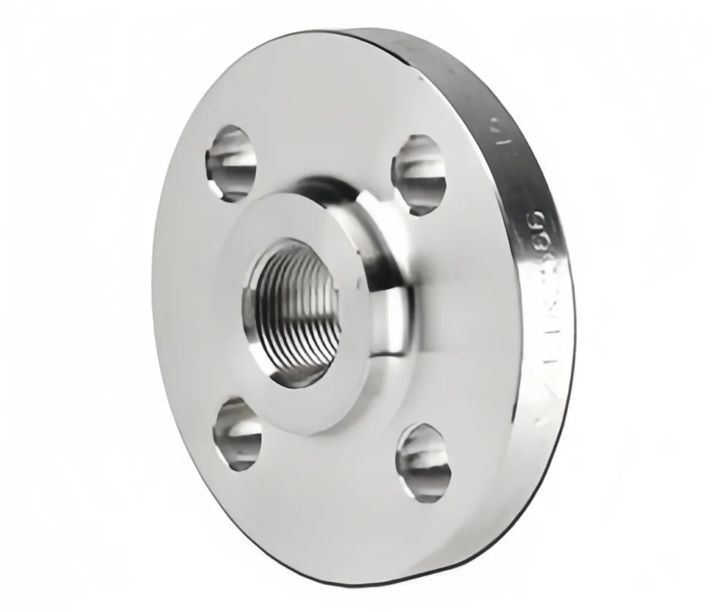
Threaded Flange
 |
 |
|
|
1. Materials:
Carbon Steel: ASTM A105, ASTM A350 LF1, LF2, LF3, A36, 16Mn, etc
Stainless Steel: ASTM A 182, A 240 F 304, 304L, 304H, 316, 316L, 316Ti, 310, 310S, 321, 321H, 317, 347, 347H, 904L
Alloy Steel: A182 F1, F5, F9, F11, F12, 22, F22, F91, etc
Duplex Stainless Steel: ASTM A 182 – F51, F53, F55, S31803, S32205, S32550, S31254, SMO254, S32750, S32760, S32950.
Copper Alloy Steel: ASTM / ASME SB 111 UNS NO. C 10100, C 10200, C 10300, C 10800, C 12000, C 12200, C 70600, C 71500, ASTM / ASME SB 466 UNS NO. C 70600 ( CU -NI- 90/10), C 71500 ( CU -NI- 70/30)
Nickel Alloy: ASTM / ASME SB 336, ASTM / ASME SB 564 / 160 / 163 / 472, UNS 2200 (NICKEL 200), UNS 2201 (NICKEL 201 ), UNS 4400 (MONEL 400 ), UNS 8020 ( ALLOY 20 / 20 CB 3 ), UNS 8825 INCONEL (825), UNS 6600 (INCONEL 600 ), UNS 6601 (INCONEL 601), UNS 6625 (INCONEL 625), UNS 10276 (HASTELLOY C 276)
For detial dimensions and catalogue of Reducing Flanges please contact with us now sales@attpipeline.com
2. Standards:
ANSI/ASME B16.5, B16.36, B16.47, AWWA C207, DIN, BS, SABS/SANS, MSS SP44, ISO, API Flange, etc
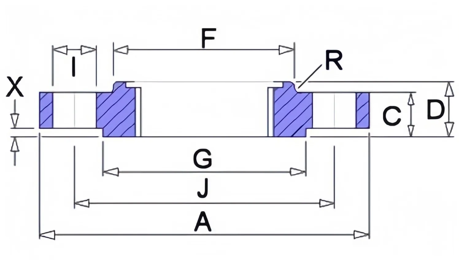
Dimensions & Masses of ANSI B16.5 Threaded Flange Class 150/300/600
| ANSI, ASME, ASA, B16.5 150lb/sq.in. Threaded Flange NPT | |||||||||||
| Pipe | Flange Data | Hub Data | Raised Face | Drilling Data | Weight | ||||||
| Nominal Size | A | C | D | E | F | G | H | I | J | ||
| Outside Dia | Overall Dia | Flange Thickness min | Overall Length | Threaded Length min | Hub Dia | Face Dia | Number of Holes | Bolt Hole Dia | Dia of Circle of Holes | Kg/ Piece | |
| In Mm | In Mm | In Mm | In Mm | In Mm | In Mm | In Mm | In Mm | In Mm | |||
| ½ | 0.84 | 3.5 | 0.44 | 0.62 | 0.62 | 1.19 | 1.38 | 4 | 0.62 | 2.38 | 0.39 |
| 21.3 | 88.9 | 11.2 | 15.7 | 15.7 | 30.2 | 35.1 | 15.7 | 60.45 | |||
| ¾ | 1.05 | 3.88 | 0.5 | 0.62 | 0.62 | 1.5 | 1.69 | 4 | 0.62 | 2.75 | 0.56 |
| 26.7 | 98.6 | 12.7 | 15.7 | 15.7 | 38.1 | 42.9 | 15.7 | 69.85 | |||
| 1 | 1.315 | 4.25 | 0.56 | 0.69 | 0.69 | 1.94 | 2 | 4 | 0.62 | 3.12 | 0.78 |
| 33.4 | 108 | 14.2 | 17.5 | 17.5 | 49.3 | 50.8 | 15.7 | 79.25 | |||
| 1 ¼ | 1.66 | 4.62 | 0.62 | 0.81 | 0.81 | 2.31 | 2.5 | 4 | 0.62 | 3.5 | 1.03 |
| 42.2 | 117.3 | 15.7 | 20.6 | 20.6 | 58.7 | 63.5 | 15.7 | 88.9 | |||
| 1 ½ | 1.9 | 5 | 0.69 | 0.88 | 0.88 | 2.56 | 2.88 | 4 | 0.62 | 3.88 | 1.32 |
| 48.3 | 127 | 17.5 | 22.4 | 22.4 | 65 | 73.15 | 15.7 | 98.6 | |||
| 2 | 2.375 | 6 | 0.75 | 1 | 1 | 3.06 | 3.62 | 4 | 0.75 | 4.75 | 2.06 |
| 60.3 | 152.4 | 19.1 | 25.4 | 25.4 | 77.7 | 91.9 | 19.1 | 120.7 | |||
| 2 ½ | 2.875 | 7 | 0.88 | 1.12 | 1.12 | 3.56 | 4.12 | 4 | 0.75 | 5.5 | 3.28 |
| 73 | 177.8 | 22.4 | 28.4 | 28.4 | 90.4 | 104.6 | 19.1 | 139.7 | |||
| 3 | 3.5 | 7.5 | 0.94 | 1.19 | 1.19 | 4.25 | 5 | 4 | 0.75 | 6 | 3.85 |
| 88.9 | 190.5 | 23.9 | 30.2 | 30.2 | 108 | 127 | 19.1 | 152.4 | |||
| 3 ½ | 4 | 8.5 | 0.94 | 1.25 | 1.25 | 4.81 | 5.5 | 8 | 0.75 | 7 | 4.81 |
| 101.6 | 215.9 | 23.9 | 31.75 | 31.75 | 122.2 | 139.7 | 19.1 | 177.8 | |||
| 4 | 4.5 | 9 | 0.94 | 1.31 | 1.31 | 5.31 | 6.19 | 8 | 0.75 | 7.5 | 5.3 |
| 114.3 | 228.6 | 23.9 | 33.3 | 33.3 | 134.9 | 157.2 | 19.1 | 190.5 | |||
| 5 | 5.563 | 10 | 0.94 | 1.44 | 1.44 | 6.44 | 7.31 | 8 | 0.88 | 8.5 | 6.07 |
| 141.3 | 254 | 23.9 | 36.6 | 36.6 | 163.6 | 185.7 | 22.4 | 215.9 | |||
| 6 | 6.625 | 11 | 1 | 1.56 | 1.56 | 7.56 | 8.5 | 8 | 0.88 | 9.5 | 7.45 |
| 168.3 | 279.4 | 25.4 | 39.6 | 39.6 | 192 | 215.9 | 22.4 | 241.3 | |||
| 8 | 8.625 | 13.5 | 1.12 | 1.75 | 1.75 | 9.69 | 10.62 | 8 | 0.88 | 11.75 | 12.1 |
| 219.1 | 342.9 | 28.4 | 44.5 | 44.5 | 246.1 | 269.7 | 22.4 | 298.5 | |||
| 10 | 10.75 | 16 | 1.19 | 1.94 | 1.94 | 12 | 12.75 | 12 | 1 | 14.25 | 16.5 |
| 273 | 406.4 | 30.2 | 49.3 | 49.3 | 304.8 | 323.8 | 25.4 | 362 | |||
| 12 | 12.75 | 19 | 1.25 | 2.19 | 2.19 | 14.38 | 15 | 12 | 1 | 17 | 26.2 |
| 323.8 | 482.6 | 31.75 | 55.6 | 55.6 | 365.3 | 381 | 25.4 | 431.8 | |||
| 14 | 14 | 21 | 1.38 | 2.25 | 2.25 | 15.75 | 16.25 | 12 | 1.12 | 18.75 | 34.6 |
| 355.6 | 533.4 | 35.1 | 57.15 | 57.15 | 400.1 | 412.7 | 28.4 | 476.3 | |||
| 16 | 16 | 23.5 | 1.44 | 2.5 | 2.5 | 18 | 18.5 | 16 | 1.12 | 21.25 | 44.8 |
| 406.4 | 596.9 | 36.6 | 63.5 | 63.5 | 457.2 | 469.9 | 28.4 | 539.8 | |||
| 18 | 18 | 25 | 1.56 | 2.69 | 2.69 | 19.88 | 21 | 16 | 1.25 | 22.75 | 48.9 |
| 457.2 | 635 | 39.6 | 68.3 | 68.3 | 505 | 533.4 | 31.75 | 577.9 | |||
| 20 | 20 | 27.5 | 1.69 | 2.88 | 2.88 | 22 | 23 | 20 | 1.25 | 25 | 61.9 |
| 508 | 698.5 | 42.9 | 73.15 | 73.15 | 558.8 | 584.2 | 31.75 | 635 | |||
| 24 | 24 | 32 | 1.88 | 3.25 | 3.25 | 26.12 | 27.25 | 20 | 1.38 | 29.5 | 86.9 |
| 609.6 | 812.8 | 47.8 | 82.6 | 82.6 | 663.4 | 692.1 | 35.1 | 749.3 | |||
NOTE:
1. The thread conforms to ASME B1.20.1 NTP threads as described in Section 10. (The only exceptions are small male and female plain face threaded flanges which use NPSL recount threads.)
2. Class 150 threaded flanges are made without a counterbore. Threads are chamfered to the major diameter (approx.) at an angle of 45° (approx.) at the back of the flange.
3. Weights are based on manufacturer's data and are approximate.
4. For tolerances +-0.5mm.
| ANSI, ASME, ASA, B16.5 300lb/sq.in. Threaded Flange NPT | ||||||||||||
| Pipe | Flange Data | Hub Data | Raised Face | Drilling Data | Weight | |||||||
| Nominal Size | A | B | C | D | E | F | G | H | I | J | ||
| Outside Dia | Overall Dia | Counter Bore | Flange Thickness min | Overall Length | Threaded Length min | Hub Dia | Face Dia | Number of Holes | Bolt Hole Dia | Dia of Circle of Holes | Kg/ Piece | |
| In Mm | In Mm | In Mm | In Mm | In Mm | In Mm | In Mm | In Mm | In Mm | In Mm | |||
| ½ | 0.84 | 3.75 | 0.93 | 0.56 | 0.88 | 0.62 | 1.5 | 1.38 | 4 | 0.62 | 2.62 | 0.64 |
| 21.3 | 95.3 | 23.6 | 14.2 | 22.3 | 15.7 | 38.1 | 35 | 15.7 | 66.55 | |||
| ¾ | 1.05 | 4.62 | 1.14 | 0.62 | 1 | 0.62 | 1.88 | 1.69 | 4 | 0.75 | 3.25 | 1.12 |
| 26.7 | 117.3 | 29 | 15.7 | 25.4 | 15.7 | 42.7 | 42.9 | 19 | 82.5 | |||
| 1 | 1.315 | 4.88 | 1.41 | 0.69 | 1.06 | 0.69 | 2.12 | 2 | 4 | 0.75 | 3.5 | 1.36 |
| 33.4 | 124 | 35.8 | 17.5 | 26.9 | 17.5 | 53.8 | 50.8 | 19 | 88.9 | |||
| 1 ¼ | 1.66 | 5.25 | 1.75 | 0.75 | 1.06 | 0.81 | 2.5 | 2.5 | 4 | 0.75 | 3.88 | 1.68 |
| 42.2 | 133.4 | 44.4 | 19 | 26.9 | 20.6 | 63.5 | 63.5 | 19 | 98.5 | |||
| 1 ½ | 1.9 | 6.12 | 1.99 | 0.81 | 1.19 | 0.88 | 2.75 | 2.88 | 4 | 0.88 | 4.5 | 2.49 |
| 48.3 | 155.4 | 50.5 | 20.6 | 30.2 | 22.3 | 69.85 | 73.15 | 22.3 | 114.3 | |||
| 2 | 2.375 | 6.5 | 2.5 | 0.88 | 1.31 | 1.12 | 3.31 | 3.62 | 8 | 0.75 | 5 | 2.87 |
| 60.3 | 165.1 | 63.5 | 22.3 | 33.2 | 28.4 | 84 | 91.9 | 19 | 127 | |||
| 2 ½ | 2.875 | 7.5 | 3 | 1 | 1.5 | 1.25 | 3.94 | 4.12 | 8 | 0.88 | 5.88 | 4.32 |
| 73 | 190.5 | 76.2 | 25.4 | 38.1 | 31.7 | 100 | 104.6 | 22.3 | 149.3 | |||
| 3 | 3.5 | 8.25 | 3.63 | 1.12 | 1.69 | 1.25 | 4.62 | 5 | 8 | 0.88 | 6.62 | 5.85 |
| 88.9 | 209.6 | 92.2 | 28.4 | 42.9 | 31.7 | 117.3 | 127 | 22.3 | 168.1 | |||
| 3 ½ | 4 | 9 | 4.13 | 1.19 | 1.75 | 1.44 | 5.25 | 5.5 | 8 | 0.88 | 7.25 | 7.34 |
| 101.6 | 228.6 | 104.9 | 30.2 | 44.4 | 36.5 | 133.3 | 139.7 | 22.3 | 184.1 | |||
| 4 | 4.5 | 10 | 4.63 | 1.25 | 1.88 | 1.44 | 5.75 | 6.19 | 8 | 0.88 | 7.88 | 9.61 |
| 114.3 | 254 | 117.6 | 31.7 | 47.7 | 36.5 | 146 | 157.2 | 22.3 | 200.1 | |||
| 5 | 5.563 | 11 | 5.69 | 1.38 | 2 | 1.69 | 7 | 7.31 | 8 | 0.88 | 9.25 | 12.3 |
| 141.3 | 279.4 | 144.5 | 35 | 50.8 | 42.9 | 177.8 | 185.7 | 22.3 | 234.9 | |||
| 6 | 6.625 | 12.5 | 6.75 | 1.44 | 2.06 | 1.81 | 8.12 | 8.5 | 12 | 0.88 | 10.62 | 15.6 |
| 168.3 | 317.5 | 171.4 | 36.5 | 52.3 | 45.9 | 206.2 | 215.9 | 22.3 | 269.7 | |||
| 8 | 8.625 | 15 | 8.75 | 1.62 | 2.44 | 2 | 10.25 | 10.62 | 12 | 1 | 13 | 24.2 |
| 219.1 | 381 | 222.3 | 41.1 | 61.9 | 50.8 | 260.3 | 269.7 | 25.4 | 330.2 | |||
| 10 | 10.75 | 17.5 | 10.88 | 1.88 | 2.62 | 2.19 | 12.62 | 12.75 | 16 | 1.12 | 15.25 | 34.1 |
| 273 | 444.5 | 276.3 | 47.7 | 66.55 | 55.6 | 320.5 | 323.8 | 28.4 | 387.3 | |||
| 12 | 12.75 | 20.5 | 12.94 | 2 | 2.88 | 2.38 | 14.75 | 15 | 16 | 1.25 | 17.75 | 49.8 |
| 323.8 | 520.7 | 328.7 | 50.8 | 73.15 | 60.45 | 374.6 | 381 | 31.7 | 450.8 | |||
| 14 | 14 | 23 | 14.19 | 2.12 | 3 | 2.5 | 16.75 | 16.25 | 20 | 1.25 | 20.25 | 69.9 |
| 355.6 | 584.2 | 360.4 | 53.8 | 76.2 | 63.5 | 425.4 | 412.7 | 31.7 | 514.3 | |||
| 16 | 16 | 25.5 | 16.19 | 2.25 | 3.25 | 2.69 | 19 | 18.5 | 20 | 1.38 | 22.5 | 88.1 |
| 406.4 | 647.7 | 411.2 | 57.15 | 82.5 | 68.3 | 482.6 | 469.9 | 35 | 571.5 | |||
| 18 | 18 | 28 | 18.19 | 2.38 | 3.5 | 2.75 | 21 | 21 | 24 | 1.38 | 24.75 | 109 |
| 457.2 | 711.2 | 462 | 60.45 | 88.9 | 69.85 | 533.4 | 533.4 | 35 | 628.6 | |||
| 20 | 20 | 30.5 | 20.19 | 2.5 | 3.75 | 2.88 | 23.12 | 23 | 24 | 1.38 | 27 | 134 |
| 508 | 774.7 | 512.8 | 63.5 | 95.2 | 73.15 | 587.2 | 584.2 | 35 | 685.8 | |||
| 24 | 24 | 36 | 24.19 | 2.75 | 4.19 | 3.25 | 27.62 | 27.25 | 24 | 1.62 | 32 | 201 |
| 609.6 | 914.4 | 614.4 | 69.85 | 106.4 | 82.5 | 701.5 | 692.1 | 41.1 | 812.8 | |||
NOTE:
1. Class 300 flanges except Lap Joint will be furnished with 0.06 (1.6mm) raised face, which is included in ‘Thickness’ (C) and ‘Length through Hub’ (Y1), (Y3).
2. For Slip-on, Threaded, Socket Welding and Lap Joint Flanges, the hubs can be shaped either vertical from base to top or tapered within the limits of 7 degrees.
3. Blind Flanges may be made with the same hub as that used for Slip-on Flanges or without hub.
4. The gasket surface and backside (bearing surface for bolting) are made parallel within 1 degree. To accomplish parallelism, spot facing is carried out according to MSS SP-9, without reducing thickness (C).
5. Depth of Socket (D) is covered by ANSI B 16.5 only in sizes through 3 inch, over 3 inch is at the manufacturer’s option.
| ANSI, ASME, ASA, B16.5 600lb/sq.in. Threaded Flange NPT | ||||||||||||
| Pipe | Flange Data | Hub Data | Raised Face | Drilling Data | Weight | |||||||
| A | B | C | D | E | F | G | H | I | J | |||
| Nominal Size | Outside Dia | Overall Dia | Counter Bore | Flange Thickness min | Overall Length | Threaded Length min | Hub Dia | Face Dia | Number of Holes | Bolt Hole Dia | Dia of Circle of Holes | Kg/ Piece |
| In Mm | In Mm | In Mm | In Mm | In Mm | In Mm | In Mm | In Mm | In Mm | In Mm | |||
| ½ | 0.84 | 3.75 | 0.93 | 0.56 | 0.88 | 0.62 | 1.5 | 1.38 | 4 | 0.62 | 2.62 | 0.74 |
| 21.3 | 95.3 | 23.6 | 14.2 | 22.4 | 15.7 | 38.1 | 35 | 15.7 | 66.55 | |||
| ¾ | 1.05 | 4.62 | 1.14 | 0.62 | 1 | 0.62 | 1.88 | 1.69 | 4 | 0.75 | 3.25 | 1.27 |
| 26.7 | 117.3 | 29 | 15.7 | 25.4 | 15.7 | 47.8 | 42.9 | 19.1 | 82.6 | |||
| 1 | 1.315 | 4.88 | 1.41 | 0.69 | 1.12 | 0.69 | 2.12 | 2 | 4 | 0.75 | 3.5 | 1.52 |
| 33.4 | 124 | 35.8 | 17.5 | 28.4 | 17.5 | 53.8 | 50.8 | 19.1 | 88.9 | |||
| 1 ¼ | 1.66 | 5.25 | 1.75 | 0.81 | 1.12 | 0.81 | 2.5 | 2.5 | 4 | 0.75 | 3.88 | 2.03 |
| 42.2 | 133.4 | 44.4 | 20.6 | 28.4 | 20.6 | 63.5 | 63.5 | 19.1 | 98.6 | |||
| 1 ½ | 1.9 | 6.12 | 1.99 | 0.88 | 1.25 | 0.88 | 2.75 | 2.88 | 4 | 0.88 | 4.5 | 2.96 |
| 48.3 | 155.4 | 50.5 | 22.4 | 31.75 | 22.4 | 69.85 | 73.15 | 22.4 | 114.3 | |||
| 2 | 2.375 | 6.5 | 2.5 | 1 | 1.44 | 1.12 | 3.31 | 3.62 | 8 | 0.75 | 5 | 3.62 |
| 60.3 | 165.1 | 63.5 | 25.4 | 36.6 | 28.4 | 84.1 | 91.9 | 19.1 | 127 | |||
| 2 ½ | 2.875 | 7.5 | 3 | 1.12 | 1.62 | 1.25 | 3.94 | 4.12 | 8 | 0.88 | 5.88 | 5.28 |
| 73 | 190.5 | 76.2 | 28.4 | 41.1 | 31.75 | 100.1 | 104.6 | 22.4 | 149.4 | |||
| 3 | 3.5 | 8.25 | 3.63 | 1.25 | 1.81 | 1.38 | 4.62 | 5 | 8 | 0.88 | 6.62 | 7 |
| 88.9 | 209.6 | 92.2 | 31.75 | 46 | 35.1 | 117.3 | 127 | 22.4 | 168.1 | |||
| 3 ½ | 4 | 9 | 4.13 | 1.38 | 1.94 | 1.56 | 5.25 | 5.5 | 8 | 1 | 7.25 | 8.84 |
| 101.6 | 228.6 | 104.9 | 35.1 | 49.3 | 39.6 | 133.4 | 139.7 | 25.4 | 184.2 | |||
| 4 | 4.5 | 10.75 | 4.63 | 1.5 | 2.12 | 1.62 | 6 | 6.19 | 8 | 1 | 8.5 | 14.5 |
| 114.3 | 273.1 | 117.6 | 38.1 | 53.8 | 41.1 | 152.4 | 157.2 | 25.4 | 215.9 | |||
| 5 | 5.563 | 13 | 5.69 | 1.75 | 2.38 | 1.88 | 7.44 | 7.31 | 8 | 1.12 | 10.5 | 24.4 |
| 141.3 | 330.2 | 144.5 | 44.5 | 60.45 | 47.8 | 189 | 185.7 | 28.4 | 266.7 | |||
| 6 | 6.625 | 14 | 6.75 | 1.88 | 2.62 | 2 | 8.75 | 8.5 | 12 | 1.12 | 11.5 | 28.7 |
| 168.3 | 355.6 | 171.4 | 47.8 | 66.55 | 50.8 | 222.3 | 215.9 | 28.4 | 292.1 | |||
| 8 | 8.625 | 16.5 | 8.75 | 2.19 | 3 | 2.25 | 10.75 | 10.62 | 12 | 1.25 | 13.75 | 43.4 |
| 219.1 | 419.1 | 222.3 | 55.6 | 76.2 | 57.15 | 273.1 | 269.7 | 31.75 | 349.3 | |||
| 10 | 10.75 | 20 | 10.88 | 2.5 | 3.38 | 2.56 | 13.5 | 12.75 | 16 | 1.38 | 17 | 70.3 |
| 273 | 508 | 276.3 | 63.5 | 85.9 | 65 | 342.9 | 323.8 | 35.1 | 431.8 | |||
| 12 | 12.75 | 22 | 12.94 | 2.62 | 3.62 | 2.75 | 15.75 | 15 | 20 | 1.38 | 19.25 | 84.2 |
| 323.8 | 558.8 | 328.7 | 66.55 | 91.9 | 69.85 | 400.1 | 381 | 35.1 | 489 | |||
| 14 | 14 | 23.75 | 14.19 | 2.75 | 3.69 | 2.88 | 17 | 16.25 | 20 | 1.5 | 20.75 | 98.7 |
| 355.6 | 603.3 | 360.4 | 69.85 | 93.7 | 73.15 | 431.8 | 412.7 | 38.1 | 527.1 | |||
| 16 | 16 | 27 | 16.19 | 3 | 4.19 | 3.06 | 19.5 | 18.5 | 20 | 1.62 | 23.75 | 142 |
| 406.4 | 685.8 | 411.2 | 76.2 | 106.4 | 77.7 | 495.3 | 469.9 | 41.1 | 603.3 | |||
| 18 | 18 | 29.25 | 18.19 | 3.25 | 4.62 | 3.12 | 21.5 | 21 | 20 | 1.75 | 25.75 | 173 |
| 457.2 | 743 | 462 | 82.6 | 117.3 | 79.25 | 546.1 | 533.4 | 44.5 | 654.1 | |||
| 20 | 20 | 32 | 20.19 | 3.5 | 5 | 3.25 | 24 | 23 | 24 | 1.75 | 28.5 | 220 |
| 508 | 812.8 | 512.8 | 88.9 | 127 | 82.6 | 609.6 | 584.2 | 44.5 | 723.9 | |||
| 24 | 24 | 37 | 24.19 | 4 | 5.5 | 3.62 | 28.25 | 27.25 | 24 | 2 | 33 | 312 |
| 609.6 | 939.8 | 614.4 | 101.6 | 139.7 | 91.9 | 717.6 | 692.1 | 50.8 | 838.2 | |||
NOTE:
1. Class 600 flanges except Lap Joint will be furnished with 0.06 (1.6mm) raised face, which is included in ‘Thickness’ (C) and ‘Length through Hub’ (Y1), (Y3).
2. For Slip-on, Threaded, Socket Welding and Lap Joint Flanges, the hubs can be shaped either vertical from base to top or tapered within the limits of 7 degrees.
3. Blind Flanges may be made with the same hub as that used for Slip-on Flanges or without hub.
4. The gasket surface and backside (bearing surface for bolting) are made parallel within 1 degree. To accomplish parallelism, spot facing is carried out according to MSS SP-9, without reducing thickness (C).
5. Depth of Socket (D) is covered by ANSI B 16.5 only in sizes through 3 inch, over 3 inch is at the manufacturer’s option.
2. Standards:
ANSI/ASME B16.5, B16.36, B16.47, AWWA C207, DIN, BS, SABS/SANS, MSS SP44, ISO, API Flange, etc
Dimensions & Masses of ANSI B16.5 Threaded Flange Class 150/300/600
| ANSI, ASME, ASA, B16.5 150lb/sq.in. Threaded Flange NPT | |||||||||||
| Pipe | Flange Data | Hub Data | Raised Face | Drilling Data | Weight | ||||||
| Nominal Size | A | C | D | E | F | G | H | I | J | ||
| Outside Dia | Overall Dia | Flange Thickness min | Overall Length | Threaded Length min | Hub Dia | Face Dia | Number of Holes | Bolt Hole Dia | Dia of Circle of Holes | Kg/ Piece | |
| In Mm | In Mm | In Mm | In Mm | In Mm | In Mm | In Mm | In Mm | In Mm | |||
| ½ | 0.84 | 3.5 | 0.44 | 0.62 | 0.62 | 1.19 | 1.38 | 4 | 0.62 | 2.38 | 0.39 |
| 21.3 | 88.9 | 11.2 | 15.7 | 15.7 | 30.2 | 35.1 | 15.7 | 60.45 | |||
| ¾ | 1.05 | 3.88 | 0.5 | 0.62 | 0.62 | 1.5 | 1.69 | 4 | 0.62 | 2.75 | 0.56 |
| 26.7 | 98.6 | 12.7 | 15.7 | 15.7 | 38.1 | 42.9 | 15.7 | 69.85 | |||
| 1 | 1.315 | 4.25 | 0.56 | 0.69 | 0.69 | 1.94 | 2 | 4 | 0.62 | 3.12 | 0.78 |
| 33.4 | 108 | 14.2 | 17.5 | 17.5 | 49.3 | 50.8 | 15.7 | 79.25 | |||
| 1 ¼ | 1.66 | 4.62 | 0.62 | 0.81 | 0.81 | 2.31 | 2.5 | 4 | 0.62 | 3.5 | 1.03 |
| 42.2 | 117.3 | 15.7 | 20.6 | 20.6 | 58.7 | 63.5 | 15.7 | 88.9 | |||
| 1 ½ | 1.9 | 5 | 0.69 | 0.88 | 0.88 | 2.56 | 2.88 | 4 | 0.62 | 3.88 | 1.32 |
| 48.3 | 127 | 17.5 | 22.4 | 22.4 | 65 | 73.15 | 15.7 | 98.6 | |||
| 2 | 2.375 | 6 | 0.75 | 1 | 1 | 3.06 | 3.62 | 4 | 0.75 | 4.75 | 2.06 |
| 60.3 | 152.4 | 19.1 | 25.4 | 25.4 | 77.7 | 91.9 | 19.1 | 120.7 | |||
| 2 ½ | 2.875 | 7 | 0.88 | 1.12 | 1.12 | 3.56 | 4.12 | 4 | 0.75 | 5.5 | 3.28 |
| 73 | 177.8 | 22.4 | 28.4 | 28.4 | 90.4 | 104.6 | 19.1 | 139.7 | |||
| 3 | 3.5 | 7.5 | 0.94 | 1.19 | 1.19 | 4.25 | 5 | 4 | 0.75 | 6 | 3.85 |
| 88.9 | 190.5 | 23.9 | 30.2 | 30.2 | 108 | 127 | 19.1 | 152.4 | |||
| 3 ½ | 4 | 8.5 | 0.94 | 1.25 | 1.25 | 4.81 | 5.5 | 8 | 0.75 | 7 | 4.81 |
| 101.6 | 215.9 | 23.9 | 31.75 | 31.75 | 122.2 | 139.7 | 19.1 | 177.8 | |||
| 4 | 4.5 | 9 | 0.94 | 1.31 | 1.31 | 5.31 | 6.19 | 8 | 0.75 | 7.5 | 5.3 |
| 114.3 | 228.6 | 23.9 | 33.3 | 33.3 | 134.9 | 157.2 | 19.1 | 190.5 | |||
| 5 | 5.563 | 10 | 0.94 | 1.44 | 1.44 | 6.44 | 7.31 | 8 | 0.88 | 8.5 | 6.07 |
| 141.3 | 254 | 23.9 | 36.6 | 36.6 | 163.6 | 185.7 | 22.4 | 215.9 | |||
| 6 | 6.625 | 11 | 1 | 1.56 | 1.56 | 7.56 | 8.5 | 8 | 0.88 | 9.5 | 7.45 |
| 168.3 | 279.4 | 25.4 | 39.6 | 39.6 | 192 | 215.9 | 22.4 | 241.3 | |||
| 8 | 8.625 | 13.5 | 1.12 | 1.75 | 1.75 | 9.69 | 10.62 | 8 | 0.88 | 11.75 | 12.1 |
| 219.1 | 342.9 | 28.4 | 44.5 | 44.5 | 246.1 | 269.7 | 22.4 | 298.5 | |||
| 10 | 10.75 | 16 | 1.19 | 1.94 | 1.94 | 12 | 12.75 | 12 | 1 | 14.25 | 16.5 |
| 273 | 406.4 | 30.2 | 49.3 | 49.3 | 304.8 | 323.8 | 25.4 | 362 | |||
| 12 | 12.75 | 19 | 1.25 | 2.19 | 2.19 | 14.38 | 15 | 12 | 1 | 17 | 26.2 |
| 323.8 | 482.6 | 31.75 | 55.6 | 55.6 | 365.3 | 381 | 25.4 | 431.8 | |||
| 14 | 14 | 21 | 1.38 | 2.25 | 2.25 | 15.75 | 16.25 | 12 | 1.12 | 18.75 | 34.6 |
| 355.6 | 533.4 | 35.1 | 57.15 | 57.15 | 400.1 | 412.7 | 28.4 | 476.3 | |||
| 16 | 16 | 23.5 | 1.44 | 2.5 | 2.5 | 18 | 18.5 | 16 | 1.12 | 21.25 | 44.8 |
| 406.4 | 596.9 | 36.6 | 63.5 | 63.5 | 457.2 | 469.9 | 28.4 | 539.8 | |||
| 18 | 18 | 25 | 1.56 | 2.69 | 2.69 | 19.88 | 21 | 16 | 1.25 | 22.75 | 48.9 |
| 457.2 | 635 | 39.6 | 68.3 | 68.3 | 505 | 533.4 | 31.75 | 577.9 | |||
| 20 | 20 | 27.5 | 1.69 | 2.88 | 2.88 | 22 | 23 | 20 | 1.25 | 25 | 61.9 |
| 508 | 698.5 | 42.9 | 73.15 | 73.15 | 558.8 | 584.2 | 31.75 | 635 | |||
| 24 | 24 | 32 | 1.88 | 3.25 | 3.25 | 26.12 | 27.25 | 20 | 1.38 | 29.5 | 86.9 |
| 609.6 | 812.8 | 47.8 | 82.6 | 82.6 | 663.4 | 692.1 | 35.1 | 749.3 | |||
NOTE:
1. The thread conforms to ASME B1.20.1 NTP threads as described in Section 10. (The only exceptions are small male and female plain face threaded flanges which use NPSL recount threads.)
2. Class 150 threaded flanges are made without a counterbore. Threads are chamfered to the major diameter (approx.) at an angle of 45° (approx.) at the back of the flange.
3. Weights are based on manufacturer's data and are approximate.
4. For tolerances +-0.5mm.
| ANSI, ASME, ASA, B16.5 300lb/sq.in. Threaded Flange NPT | ||||||||||||
| Pipe | Flange Data | Hub Data | Raised Face | Drilling Data | Weight | |||||||
| Nominal Size | A | B | C | D | E | F | G | H | I | J | ||
| Outside Dia | Overall Dia | Counter Bore | Flange Thickness min | Overall Length | Threaded Length min | Hub Dia | Face Dia | Number of Holes | Bolt Hole Dia | Dia of Circle of Holes | Kg/ Piece | |
| In Mm | In Mm | In Mm | In Mm | In Mm | In Mm | In Mm | In Mm | In Mm | In Mm | |||
| ½ | 0.84 | 3.75 | 0.93 | 0.56 | 0.88 | 0.62 | 1.5 | 1.38 | 4 | 0.62 | 2.62 | 0.64 |
| 21.3 | 95.3 | 23.6 | 14.2 | 22.3 | 15.7 | 38.1 | 35 | 15.7 | 66.55 | |||
| ¾ | 1.05 | 4.62 | 1.14 | 0.62 | 1 | 0.62 | 1.88 | 1.69 | 4 | 0.75 | 3.25 | 1.12 |
| 26.7 | 117.3 | 29 | 15.7 | 25.4 | 15.7 | 42.7 | 42.9 | 19 | 82.5 | |||
| 1 | 1.315 | 4.88 | 1.41 | 0.69 | 1.06 | 0.69 | 2.12 | 2 | 4 | 0.75 | 3.5 | 1.36 |
| 33.4 | 124 | 35.8 | 17.5 | 26.9 | 17.5 | 53.8 | 50.8 | 19 | 88.9 | |||
| 1 ¼ | 1.66 | 5.25 | 1.75 | 0.75 | 1.06 | 0.81 | 2.5 | 2.5 | 4 | 0.75 | 3.88 | 1.68 |
| 42.2 | 133.4 | 44.4 | 19 | 26.9 | 20.6 | 63.5 | 63.5 | 19 | 98.5 | |||
| 1 ½ | 1.9 | 6.12 | 1.99 | 0.81 | 1.19 | 0.88 | 2.75 | 2.88 | 4 | 0.88 | 4.5 | 2.49 |
| 48.3 | 155.4 | 50.5 | 20.6 | 30.2 | 22.3 | 69.85 | 73.15 | 22.3 | 114.3 | |||
| 2 | 2.375 | 6.5 | 2.5 | 0.88 | 1.31 | 1.12 | 3.31 | 3.62 | 8 | 0.75 | 5 | 2.87 |
| 60.3 | 165.1 | 63.5 | 22.3 | 33.2 | 28.4 | 84 | 91.9 | 19 | 127 | |||
| 2 ½ | 2.875 | 7.5 | 3 | 1 | 1.5 | 1.25 | 3.94 | 4.12 | 8 | 0.88 | 5.88 | 4.32 |
| 73 | 190.5 | 76.2 | 25.4 | 38.1 | 31.7 | 100 | 104.6 | 22.3 | 149.3 | |||
| 3 | 3.5 | 8.25 | 3.63 | 1.12 | 1.69 | 1.25 | 4.62 | 5 | 8 | 0.88 | 6.62 | 5.85 |
| 88.9 | 209.6 | 92.2 | 28.4 | 42.9 | 31.7 | 117.3 | 127 | 22.3 | 168.1 | |||
| 3 ½ | 4 | 9 | 4.13 | 1.19 | 1.75 | 1.44 | 5.25 | 5.5 | 8 | 0.88 | 7.25 | 7.34 |
| 101.6 | 228.6 | 104.9 | 30.2 | 44.4 | 36.5 | 133.3 | 139.7 | 22.3 | 184.1 | |||
| 4 | 4.5 | 10 | 4.63 | 1.25 | 1.88 | 1.44 | 5.75 | 6.19 | 8 | 0.88 | 7.88 | 9.61 |
| 114.3 | 254 | 117.6 | 31.7 | 47.7 | 36.5 | 146 | 157.2 | 22.3 | 200.1 | |||
| 5 | 5.563 | 11 | 5.69 | 1.38 | 2 | 1.69 | 7 | 7.31 | 8 | 0.88 | 9.25 | 12.3 |
| 141.3 | 279.4 | 144.5 | 35 | 50.8 | 42.9 | 177.8 | 185.7 | 22.3 | 234.9 | |||
| 6 | 6.625 | 12.5 | 6.75 | 1.44 | 2.06 | 1.81 | 8.12 | 8.5 | 12 | 0.88 | 10.62 | 15.6 |
| 168.3 | 317.5 | 171.4 | 36.5 | 52.3 | 45.9 | 206.2 | 215.9 | 22.3 | 269.7 | |||
| 8 | 8.625 | 15 | 8.75 | 1.62 | 2.44 | 2 | 10.25 | 10.62 | 12 | 1 | 13 | 24.2 |
| 219.1 | 381 | 222.3 | 41.1 | 61.9 | 50.8 | 260.3 | 269.7 | 25.4 | 330.2 | |||
| 10 | 10.75 | 17.5 | 10.88 | 1.88 | 2.62 | 2.19 | 12.62 | 12.75 | 16 | 1.12 | 15.25 | 34.1 |
| 273 | 444.5 | 276.3 | 47.7 | 66.55 | 55.6 | 320.5 | 323.8 | 28.4 | 387.3 | |||
| 12 | 12.75 | 20.5 | 12.94 | 2 | 2.88 | 2.38 | 14.75 | 15 | 16 | 1.25 | 17.75 | 49.8 |
| 323.8 | 520.7 | 328.7 | 50.8 | 73.15 | 60.45 | 374.6 | 381 | 31.7 | 450.8 | |||
| 14 | 14 | 23 | 14.19 | 2.12 | 3 | 2.5 | 16.75 | 16.25 | 20 | 1.25 | 20.25 | 69.9 |
| 355.6 | 584.2 | 360.4 | 53.8 | 76.2 | 63.5 | 425.4 | 412.7 | 31.7 | 514.3 | |||
| 16 | 16 | 25.5 | 16.19 | 2.25 | 3.25 | 2.69 | 19 | 18.5 | 20 | 1.38 | 22.5 | 88.1 |
| 406.4 | 647.7 | 411.2 | 57.15 | 82.5 | 68.3 | 482.6 | 469.9 | 35 | 571.5 | |||
| 18 | 18 | 28 | 18.19 | 2.38 | 3.5 | 2.75 | 21 | 21 | 24 | 1.38 | 24.75 | 109 |
| 457.2 | 711.2 | 462 | 60.45 | 88.9 | 69.85 | 533.4 | 533.4 | 35 | 628.6 | |||
| 20 | 20 | 30.5 | 20.19 | 2.5 | 3.75 | 2.88 | 23.12 | 23 | 24 | 1.38 | 27 | 134 |
| 508 | 774.7 | 512.8 | 63.5 | 95.2 | 73.15 | 587.2 | 584.2 | 35 | 685.8 | |||
| 24 | 24 | 36 | 24.19 | 2.75 | 4.19 | 3.25 | 27.62 | 27.25 | 24 | 1.62 | 32 | 201 |
| 609.6 | 914.4 | 614.4 | 69.85 | 106.4 | 82.5 | 701.5 | 692.1 | 41.1 | 812.8 | |||
NOTE:
1. Class 300 flanges except Lap Joint will be furnished with 0.06 (1.6mm) raised face, which is included in ‘Thickness’ (C) and ‘Length through Hub’ (Y1), (Y3).
2. For Slip-on, Threaded, Socket Welding and Lap Joint Flanges, the hubs can be shaped either vertical from base to top or tapered within the limits of 7 degrees.
3. Blind Flanges may be made with the same hub as that used for Slip-on Flanges or without hub.
4. The gasket surface and backside (bearing surface for bolting) are made parallel within 1 degree. To accomplish parallelism, spot facing is carried out according to MSS SP-9, without reducing thickness (C).
5. Depth of Socket (D) is covered by ANSI B 16.5 only in sizes through 3 inch, over 3 inch is at the manufacturer’s option.
| ANSI, ASME, ASA, B16.5 600lb/sq.in. Threaded Flange NPT | ||||||||||||
| Pipe | Flange Data | Hub Data | Raised Face | Drilling Data | Weight | |||||||
| A | B | C | D | E | F | G | H | I | J | |||
| Nominal Size | Outside Dia | Overall Dia | Counter Bore | Flange Thickness min | Overall Length | Threaded Length min | Hub Dia | Face Dia | Number of Holes | Bolt Hole Dia | Dia of Circle of Holes | Kg/ Piece |
| In Mm | In Mm | In Mm | In Mm | In Mm | In Mm | In Mm | In Mm | In Mm | In Mm | |||
| ½ | 0.84 | 3.75 | 0.93 | 0.56 | 0.88 | 0.62 | 1.5 | 1.38 | 4 | 0.62 | 2.62 | 0.74 |
| 21.3 | 95.3 | 23.6 | 14.2 | 22.4 | 15.7 | 38.1 | 35 | 15.7 | 66.55 | |||
| ¾ | 1.05 | 4.62 | 1.14 | 0.62 | 1 | 0.62 | 1.88 | 1.69 | 4 | 0.75 | 3.25 | 1.27 |
| 26.7 | 117.3 | 29 | 15.7 | 25.4 | 15.7 | 47.8 | 42.9 | 19.1 | 82.6 | |||
| 1 | 1.315 | 4.88 | 1.41 | 0.69 | 1.12 | 0.69 | 2.12 | 2 | 4 | 0.75 | 3.5 | 1.52 |
| 33.4 | 124 | 35.8 | 17.5 | 28.4 | 17.5 | 53.8 | 50.8 | 19.1 | 88.9 | |||
| 1 ¼ | 1.66 | 5.25 | 1.75 | 0.81 | 1.12 | 0.81 | 2.5 | 2.5 | 4 | 0.75 | 3.88 | 2.03 |
| 42.2 | 133.4 | 44.4 | 20.6 | 28.4 | 20.6 | 63.5 | 63.5 | 19.1 | 98.6 | |||
| 1 ½ | 1.9 | 6.12 | 1.99 | 0.88 | 1.25 | 0.88 | 2.75 | 2.88 | 4 | 0.88 | 4.5 | 2.96 |
| 48.3 | 155.4 | 50.5 | 22.4 | 31.75 | 22.4 | 69.85 | 73.15 | 22.4 | 114.3 | |||
| 2 | 2.375 | 6.5 | 2.5 | 1 | 1.44 | 1.12 | 3.31 | 3.62 | 8 | 0.75 | 5 | 3.62 |
| 60.3 | 165.1 | 63.5 | 25.4 | 36.6 | 28.4 | 84.1 | 91.9 | 19.1 | 127 | |||
| 2 ½ | 2.875 | 7.5 | 3 | 1.12 | 1.62 | 1.25 | 3.94 | 4.12 | 8 | 0.88 | 5.88 | 5.28 |
| 73 | 190.5 | 76.2 | 28.4 | 41.1 | 31.75 | 100.1 | 104.6 | 22.4 | 149.4 | |||
| 3 | 3.5 | 8.25 | 3.63 | 1.25 | 1.81 | 1.38 | 4.62 | 5 | 8 | 0.88 | 6.62 | 7 |
| 88.9 | 209.6 | 92.2 | 31.75 | 46 | 35.1 | 117.3 | 127 | 22.4 | 168.1 | |||
| 3 ½ | 4 | 9 | 4.13 | 1.38 | 1.94 | 1.56 | 5.25 | 5.5 | 8 | 1 | 7.25 | 8.84 |
| 101.6 | 228.6 | 104.9 | 35.1 | 49.3 | 39.6 | 133.4 | 139.7 | 25.4 | 184.2 | |||
| 4 | 4.5 | 10.75 | 4.63 | 1.5 | 2.12 | 1.62 | 6 | 6.19 | 8 | 1 | 8.5 | 14.5 |
| 114.3 | 273.1 | 117.6 | 38.1 | 53.8 | 41.1 | 152.4 | 157.2 | 25.4 | 215.9 | |||
| 5 | 5.563 | 13 | 5.69 | 1.75 | 2.38 | 1.88 | 7.44 | 7.31 | 8 | 1.12 | 10.5 | 24.4 |
| 141.3 | 330.2 | 144.5 | 44.5 | 60.45 | 47.8 | 189 | 185.7 | 28.4 | 266.7 | |||
| 6 | 6.625 | 14 | 6.75 | 1.88 | 2.62 | 2 | 8.75 | 8.5 | 12 | 1.12 | 11.5 | 28.7 |
| 168.3 | 355.6 | 171.4 | 47.8 | 66.55 | 50.8 | 222.3 | 215.9 | 28.4 | 292.1 | |||
| 8 | 8.625 | 16.5 | 8.75 | 2.19 | 3 | 2.25 | 10.75 | 10.62 | 12 | 1.25 | 13.75 | 43.4 |
| 219.1 | 419.1 | 222.3 | 55.6 | 76.2 | 57.15 | 273.1 | 269.7 | 31.75 | 349.3 | |||
| 10 | 10.75 | 20 | 10.88 | 2.5 | 3.38 | 2.56 | 13.5 | 12.75 | 16 | 1.38 | 17 | 70.3 |
| 273 | 508 | 276.3 | 63.5 | 85.9 | 65 | 342.9 | 323.8 | 35.1 | 431.8 | |||
| 12 | 12.75 | 22 | 12.94 | 2.62 | 3.62 | 2.75 | 15.75 | 15 | 20 | 1.38 | 19.25 | 84.2 |
| 323.8 | 558.8 | 328.7 | 66.55 | 91.9 | 69.85 | 400.1 | 381 | 35.1 | 489 | |||
| 14 | 14 | 23.75 | 14.19 | 2.75 | 3.69 | 2.88 | 17 | 16.25 | 20 | 1.5 | 20.75 | 98.7 |
| 355.6 | 603.3 | 360.4 | 69.85 | 93.7 | 73.15 | 431.8 | 412.7 | 38.1 | 527.1 | |||
| 16 | 16 | 27 | 16.19 | 3 | 4.19 | 3.06 | 19.5 | 18.5 | 20 | 1.62 | 23.75 | 142 |
| 406.4 | 685.8 | 411.2 | 76.2 | 106.4 | 77.7 | 495.3 | 469.9 | 41.1 | 603.3 | |||
| 18 | 18 | 29.25 | 18.19 | 3.25 | 4.62 | 3.12 | 21.5 | 21 | 20 | 1.75 | 25.75 | 173 |
| 457.2 | 743 | 462 | 82.6 | 117.3 | 79.25 | 546.1 | 533.4 | 44.5 | 654.1 | |||
| 20 | 20 | 32 | 20.19 | 3.5 | 5 | 3.25 | 24 | 23 | 24 | 1.75 | 28.5 | 220 |
| 508 | 812.8 | 512.8 | 88.9 | 127 | 82.6 | 609.6 | 584.2 | 44.5 | 723.9 | |||
| 24 | 24 | 37 | 24.19 | 4 | 5.5 | 3.62 | 28.25 | 27.25 | 24 | 2 | 33 | 312 |
| 609.6 | 939.8 | 614.4 | 101.6 | 139.7 | 91.9 | 717.6 | 692.1 | 50.8 | 838.2 | |||
NOTE:
1. Class 600 flanges except Lap Joint will be furnished with 0.06 (1.6mm) raised face, which is included in ‘Thickness’ (C) and ‘Length through Hub’ (Y1), (Y3).
2. For Slip-on, Threaded, Socket Welding and Lap Joint Flanges, the hubs can be shaped either vertical from base to top or tapered within the limits of 7 degrees.
3. Blind Flanges may be made with the same hub as that used for Slip-on Flanges or without hub.
4. The gasket surface and backside (bearing surface for bolting) are made parallel within 1 degree. To accomplish parallelism, spot facing is carried out according to MSS SP-9, without reducing thickness (C).
5. Depth of Socket (D) is covered by ANSI B 16.5 only in sizes through 3 inch, over 3 inch is at the manufacturer’s option.